qiskit: Circuit incorrectly justifed
Information
- Qiskit Terra version: master
- Python version: 3.7
- Operating system: macOS
What is the current behavior?
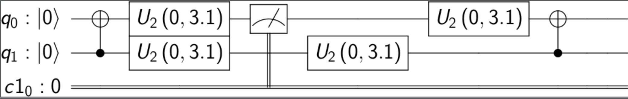
The following circuit is not correctly justified, the first U2 after the measure appears in its own column, rather than underneath the other U2.
Steps to reproduce the problem
qasm = """
OPENQASM 2.0;
include "qelib1.inc";
qreg q[5];
creg c1[1];
u2(0,3.14159265358979) q[0];
u2(0,3.14159265358979) q[1];
cx q[1],q[0];
u2(0,3.14159265358979) q[0];
u2(0,3.14159265358979) q[1];
u2(0,3.14159265358979) q[1];
measure q[0] -> c1[0];
u2(0,3.14159265358979) q[0];
cx q[1],q[0];
u2(0,3.14159265358979) q[0];
u2(0,3.14159265358979) q[1];
 """
from qiskit import QuantumCircuit
qc = QuantumCircuit.from_qasm_str(qasm)
print(qc)
        ┌──────────────┐┌───┐┌──────────────┐┌─┐                ┌──────────────┐┌───┐┌──────────────┐
q_0: |0>┤ U2(0,3.1416) ├┤ X ├┤ U2(0,3.1416) ├┤M├────────────────┤ U2(0,3.1416) ├┤ X ├┤ U2(0,3.1416) ├
        ├──────────────┤└─┬─┘├──────────────┤└╥┘┌──────────────┐└──────────────┘└─┬─┘├──────────────┤
q_1: |0>┤ U2(0,3.1416) ├──■──┤ U2(0,3.1416) ├─╫─┤ U2(0,3.1416) ├──────────────────■──┤ U2(0,3.1416) ├
        └──────────────┘     └──────────────┘ ║ └──────────────┘                     └──────────────┘
q_2: |0>──────────────────────────────────────╫──────────────────────────────────────────────────────
                                              ║
q_3: |0>──────────────────────────────────────╫──────────────────────────────────────────────────────
                                              ║
q_4: |0>──────────────────────────────────────╫──────────────────────────────────────────────────────
                                              ║
c1_0: 0 ══════════════════════════════════════╩══════════════════════════════════════════════════════
What is the expected behavior?
        ┌──────────────┐┌───┐┌──────────────┐┌─┐┌──────────────┐┌───┐┌──────────────┐
q_0: |0>┤ U2(0,3.1416) ├┤ X ├┤ U2(0,3.1416) ├┤M├┤ U2(0,3.1416) ├┤ X ├┤ U2(0,3.1416) ├
        ├──────────────┤└─┬─┘├──────────────┤└╥┘├──────────────┤└─┬─┘├──────────────┤
q_1: |0>┤ U2(0,3.1416) ├──■──┤ U2(0,3.1416) ├─╫─┤ U2(0,3.1416) ├──■──┤ U2(0,3.1416) ├
        └──────────────┘     └──────────────┘ ║ └──────────────┘     └──────────────┘
q_2: |0>──────────────────────────────────────╫──────────────────────────────────────
                                              ║
q_3: |0>──────────────────────────────────────╫──────────────────────────────────────
                                              ║
q_4: |0>──────────────────────────────────────╫──────────────────────────────────────
                                              ║
c1_0: 0 ══════════════════════════════════════╩══════════════════════════════════════
About this issue
- Original URL
- State: closed
- Created 5 years ago
- Comments: 27 (27 by maintainers)
Commits related to this issue
- Fix circuit drawing justification (#3061) Fixes #2802 qiskit/visualization/utils.py _get_layered_instructions() was erroneous and did not justify left nor right correctly. I have reworked that cod... — committed to Qiskit/qiskit by jwoehr 5 years ago
- rebase ion-trap branch (#3153) * Remove changelog and document automated creation (#3109) * Remove changelog and document automated creation With the introduction of the qiskit-bot release auto... — committed to Qiskit/qiskit by ajavadia 5 years ago
- Add initial support for working with ion-trap devices (#3214) * Add partial transpiler support for targeting ion trap backends. (#3122) * handle reset/barrier/measure (#3130) * Do not unroll an... — committed to Qiskit/qiskit by kdk 5 years ago
- Fix circuit drawing justification (#3061) Fixes #2802 qiskit/visualization/utils.py _get_layered_instructions() was erroneous and did not justify left nor right correctly. I have reworked that cod... — committed to faisaldebouni/qiskit-terra by jwoehr 5 years ago
- Add initial support for working with ion-trap devices (#3214) * Add partial transpiler support for targeting ion trap backends. (#3122) * handle reset/barrier/measure (#3130) * Do not unroll an... — committed to faisaldebouni/qiskit-terra by kdk 5 years ago
@1ucian0 , I recreate qasm for the circuit you illustrated above and test draw
left,right, andnonewith this code:The resulting output is show below. Am I correct that both
leftandrightare incorrect (leftfor the reason you pointed out above, andrightfor the positioning of the lasth q[3]) whilenoneis correct?I think the error is likely to be in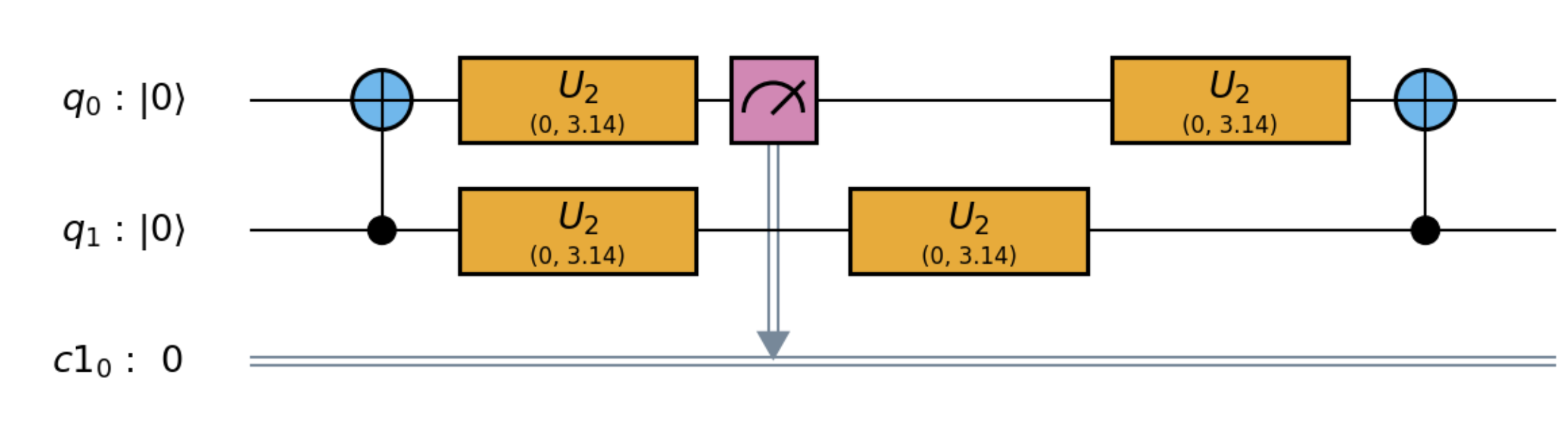
qiskit-terra/qiskit/visualization/utils.pyin the method_get_layered_instructions()as I am seeing the bug in both the mpl and the latex outputs too. It is probably an error with the way the layers are being generated rather than drawn.If you have a look at the DAG generated by the qasm you have given, it can be seen that the measure is independent of the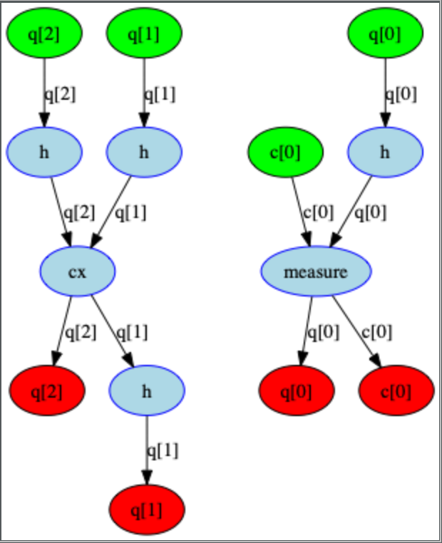 According to the networkx documentation topological sorts are non unique, which means that both the qasm order and the order returned by the DAG are valid (along with many other potential orderings!). We have found that the order the nodes are returned can vary with python versions, but ultimately they are all valid orderings.
cxand finalhso it does not matter where in the list comes in relation to them.For justification right, the H on q_2 should be on the last time slice, not the first.
Yes 😃
Okay, I think I was confused by the
measurebut sinceq[1]isn’t being measured it doesn’t matter where the secondu2[q1]appears w/r/t themessure.@jwoehr the justifications are to enable you too see the ASAP/ALAP layouts of the circuit.
leftmeans all the gates are drawn in the circuit as far to the left as possible, so the ASAP ordering.rightmeans they are drawn as far to the right, ALAP ordering.nonemeans each gate appears in its own column in the circuit.The expected behaviour in the top example is that the two
u2gates are stacked on top of eachother, as regardless of the order they were declared in they can happen at the same time.It seems like this example has the same issue (last round of
H):