esp-idf: ESP32-S2 RISC-V I2C not generating SCL clock. Getting Stuck forever during master read/write. (IDFGH-9696)
I am using ESP32-S2 MINI 1U chip for our project.
We need to fetch I2C sensors in active as well as deep sleep mode.
GPIO 2: SCL GPIO 3: SDA All pullup enabled.
Presently I am trying to initialize I2C using RISC-V drivers as follows:
static void init_i2c(void)
{
    /* Configure RTC I2C */
    printf("Initializing RTC I2C ...\n");
    ulp_riscv_i2c_cfg_t i2c_cfg = ULP_RISCV_I2C_DEFAULT_CONFIG();
    ulp_riscv_i2c_master_init(&i2c_cfg);
}
init_i2c() is invoked in app_main() before the ULP is started.
I am starting to read the chip id using following statements:
ulp_riscv_i2c_master_set_slave_addr(0x6C);
ulp_riscv_i2c_master_set_slave_reg_addr(0x18);
ulp_riscv_i2c_master_read_from_device(&data_rd, 1);
ulp_riscv_i2c_master_read_from_device() is stuck forever. Same happens for ulp_riscv_i2c_master_write_to_device() also.
I checked that the SCL line is always 3.3v. It means the master is not generating clock signal.
What could be the reason?
About this issue
- Original URL
- State: closed
- Created a year ago
- Comments: 32
@sudeep-mohanty Thanks.
But the problem is its only writing the first byte and the second byte is throwing error. Only the upper byte writing works fine.
But with main driver its working fine.
What could be the reason?
@ParthaSarathiMishra Yes I agree that the application would be better served had the APIs had a return value. Unfortunately, we can’t the change the API signature between major version updates of the SDK as it would be a breaking change and this is an upgrade which we will plan in the future.
@sudeep-mohanty Thanks for the info.
Presently the ENS is responding with following changes:
In initialization, the timeout is increased to 2sec: i2c_cfg.i2c_timing_cfg.i2c_trans_timeout = 2000;
Disabled ack checking.
But why there is no return statement for the ulp APIs? It would have been helpful for retry.
Since we are using multiple sensors, we are facing another write issue for OPT3001 light sensor. The problem is their registers are just 1 byte apart in addressing but are of 16-bit.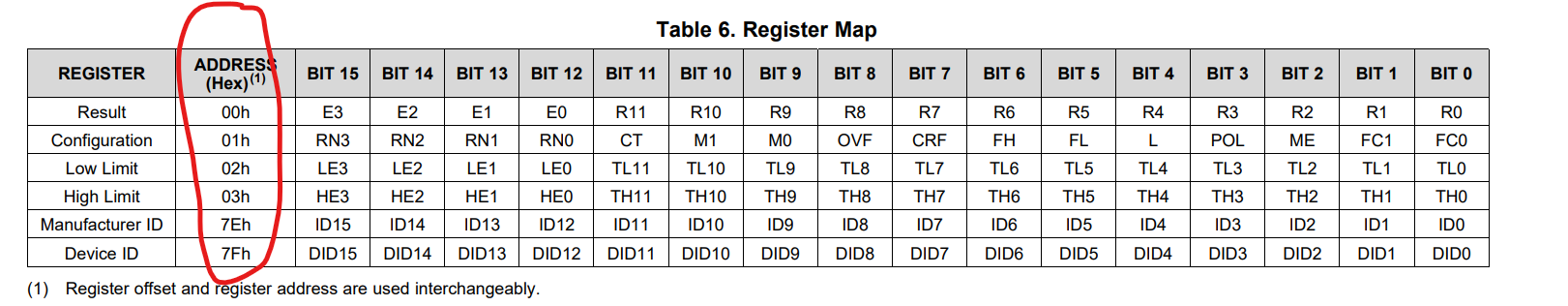
You can see 01, 02, 03 are all 16-bit registers but 1 byte apart.
To do that we tried reading the first byte as:
and second byte as:
ulp_riscv_i2c_master_read_from_device(data + 1, 2);Reading working fine.
But writing failed with following approach:
It writes only the first byte and giving error for second byte.
Here 01 and 02 are different register.
Any suggestions?
The ulp_riscv_i2c_master_read_from_device() API cannot auto increment the address from where the data is to be read. In your case, the API cannot read 1 byte from 0x00 and then automatically read the next byte from 0x01. It can only read multiple bytes from a single address.
Hello @ParthaSarathiMishra, Apologies for the delayed response to your last question. I realise that there is little or no documentation available on the RTC I2C peripheral except for the TRM docs. I will take an action on this to make the ULP RISC-V API reference guide include details about the RTC I2C peripheral. To answer your specific question, here are the major differences between the RTC I2C peripheral and the regular I2C peripheral -
Following up from your issue, here is a patch (rtc_i2c_debug.patch) to update the RTC I2C driver to be more deterministic and display some errors if something goes wrong. Could you please try this at your end and let me know your observations? Also, would it be possible for you to share an I2C analyser capture of the SDA and SCL pins when running the application?
@ParthaSarathiMishra I tried to recreate the problem that you are facing but wasn’t able to on my ESP32-S2-DevKit-C board and with the the BMP180 and BH1750 sensors. Regarding the SCL line being always pulled high, this is somewhat expected until the
I2C startcondition is generated. This should happen as soon as the following register writes are executed in theulp_riscv_i2c_master_read_from_device()call. Here is a reference capture -I did not find any reference to MC3414 being an I2C sensor but by any chance did you mean the MC3419? If so, I would try to acquire one for further tests with the RTC I2C on my end.
@sudeep-mohanty Thanks for the response. I will try.
The ulp_riscv_i2c_master_read_from_device() is called from main core. We need to make sure its working from main CPU, then only we can think of testing from ULP RISC-V core.